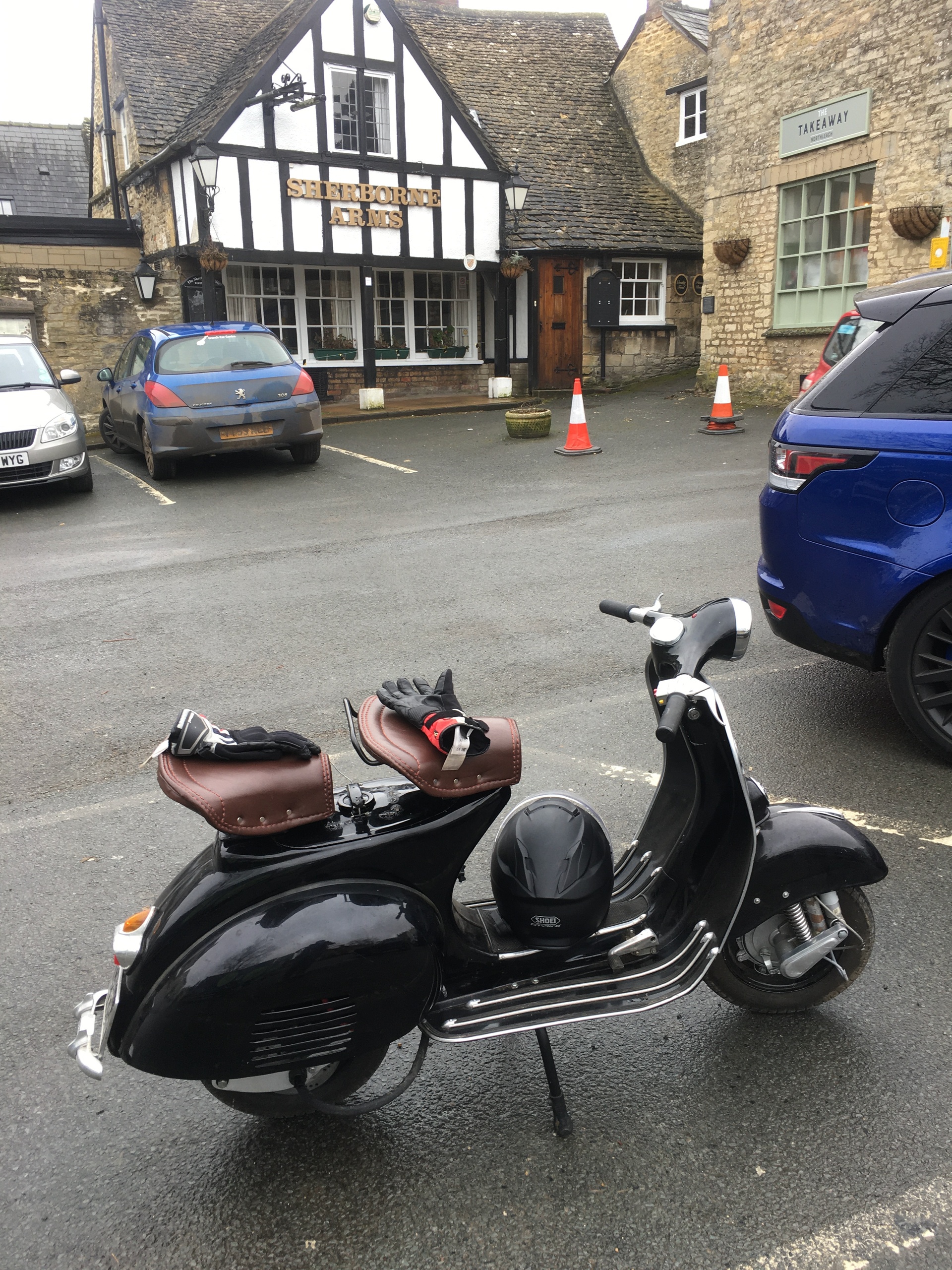
It's finished!
← back to Home
VespE
Horn
09/04/2021
I can't seem to find the right horn. I think the issue is that the bike now runs on DC power. Originally, it would have been 6V AC power straight from the engine. All of the AC horns which fit in the horn hole don't make a proper noise when 12V DC is applied. I am hoping to find one that works soon...
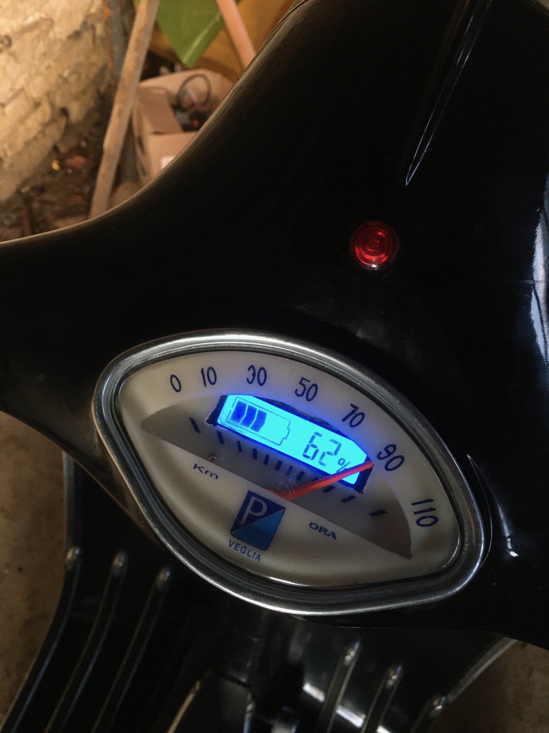
SOC indicator
15/03/2021
As usual, I plan to integrate the SOC indicator into the bike as cleanly as possible. Despite the fact that the original bike didn't have a fuel indicator at all! I have found a very small SOC indicator which I think I can cram into the original "clamshell"-type speedometer. Unfortunately, integration has been harder than I thought. These speedometers use tiny springs and worm gears to calculate and display the speed. Every time I try to cut away at the indicator backing-plate to make a hole for the SOC indicator I seem to cut one of the tiny springs or gears! I've been through two speedometers... For now, I'm going without a speedo and using the SOC indicator.
Regen braking
11/03/2021
Regen braking is much simpler to implement, as it just requires the right input to the right pin on the controller. If there was more space, I would have liked to use another pot to be able to vary the amount of regen braking: more or less depending on how far the pedal is depressed. However, given the lack of space we are just going to use Pin25 on the controller to activate/deactivate. This requires a 12V signal, which we can helpfully draw from the rear brake light, which is connected to what was the rear brake pedal. Now, when the pedal is depressed, the motor starts regen braking: delivering a small amount of power back into the motor. This has taken some testing to get the required amount of regen: too much and it's too sudden and overloads the BMS's charging capacity, too little and it doesn't slow the bike at all. There is a lingering issue that regen doesn't currently work at full charge: as the regen current is enough to trigger the BMS over-voltage protection, but that can be sorted out with software - I think...
Battery mounting 2
20/02/2021
Irritatingly, my original idea of mounting the battery inside the old fuel tank hasn't worked.
The size of these pouch cells also means they don't fit if they are all connected together in one brick.
Instead, I will split the pack into two: the "main" of 11 cells and then the "side" of 3 cells. These can be connected with high voltage wires and will function as one pack.
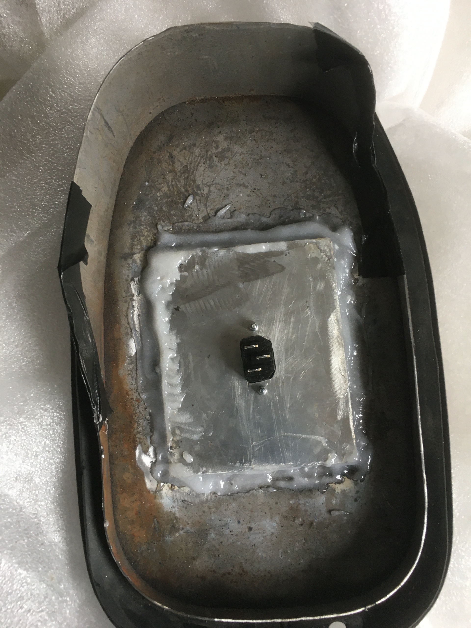
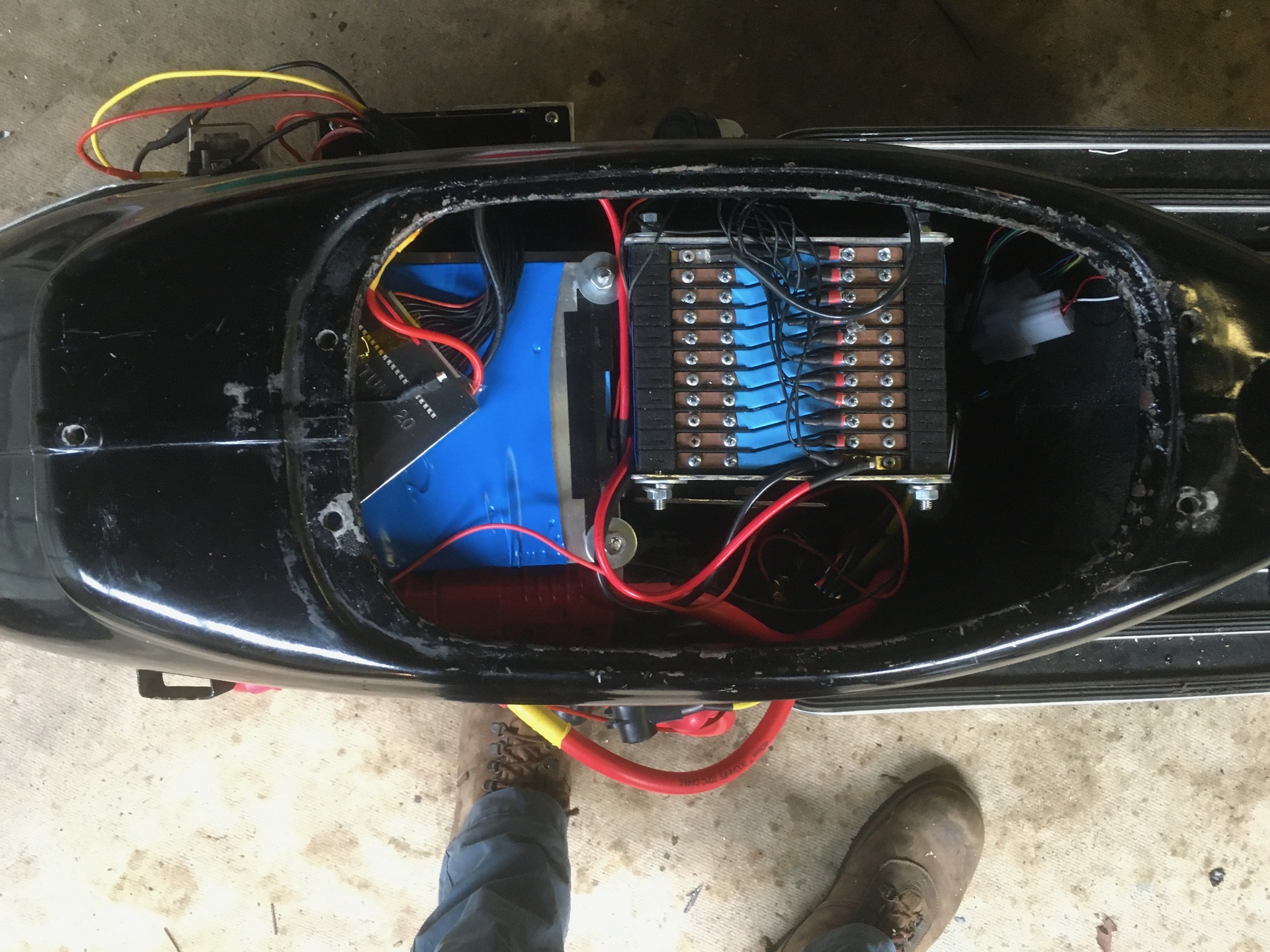 While this is a shame, I've managed to mount the charger plug within the original fuel cap. This is great and really helps with it hiding it's new electric heart!
Throttle and brake
15/02/2021
Connecting the throttle and brake has been harder than expected.
The controller expects a 0-5V signal from a potentiometer. Electric throttles that do this sort of this are available, but I am keen to keep the original throttle so that it remains looking as original as possible. I have found a 0-5V pot that I can connect to the original throttle cable.
This has been mounted to the left hand, low-voltage plate with the wires connected through to the controller.
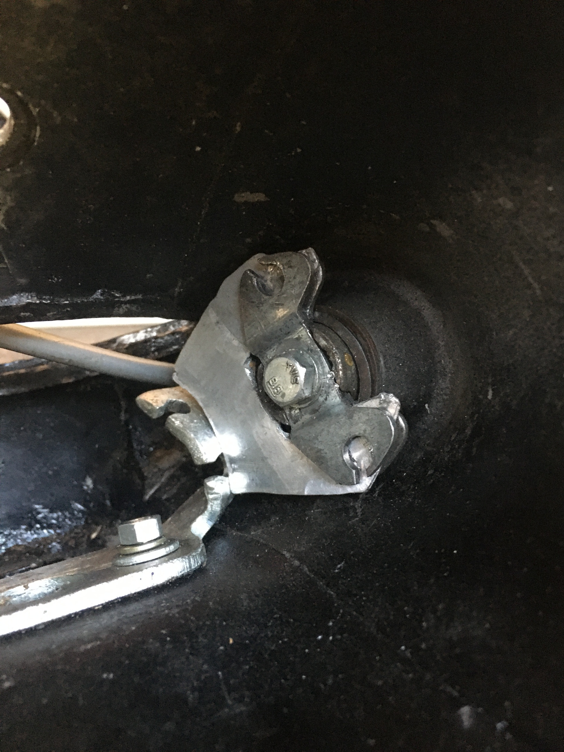
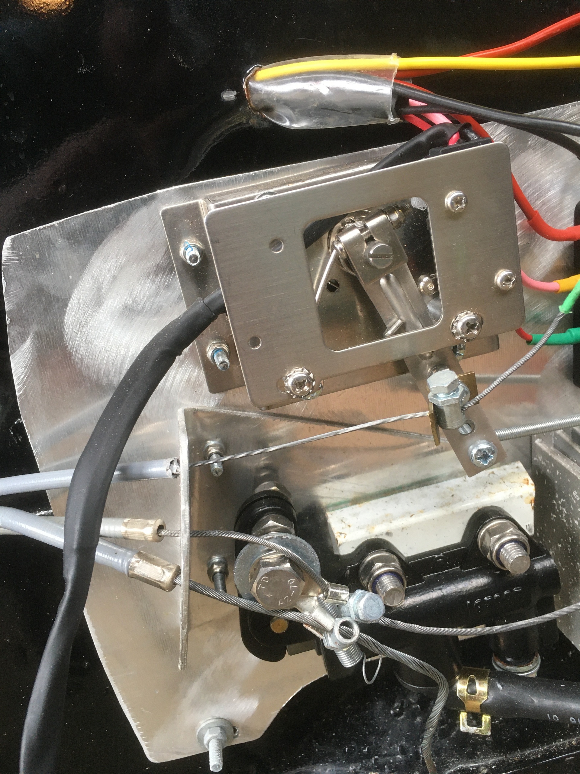 Meanwhile the rear brake has been similarly, complicated, requiring a new cable pulled through and then attached via a bolt with a hole through it to the hydraulic master cylinder.
It does look a little of a mess at the moment, but it does all work!
Meanwhile the rear brake has been similarly, complicated, requiring a new cable pulled through and then attached via a bolt with a hole through it to the hydraulic master cylinder.
It does look a little of a mess at the moment, but it does all work!
Battery Mounting
03/01/2021
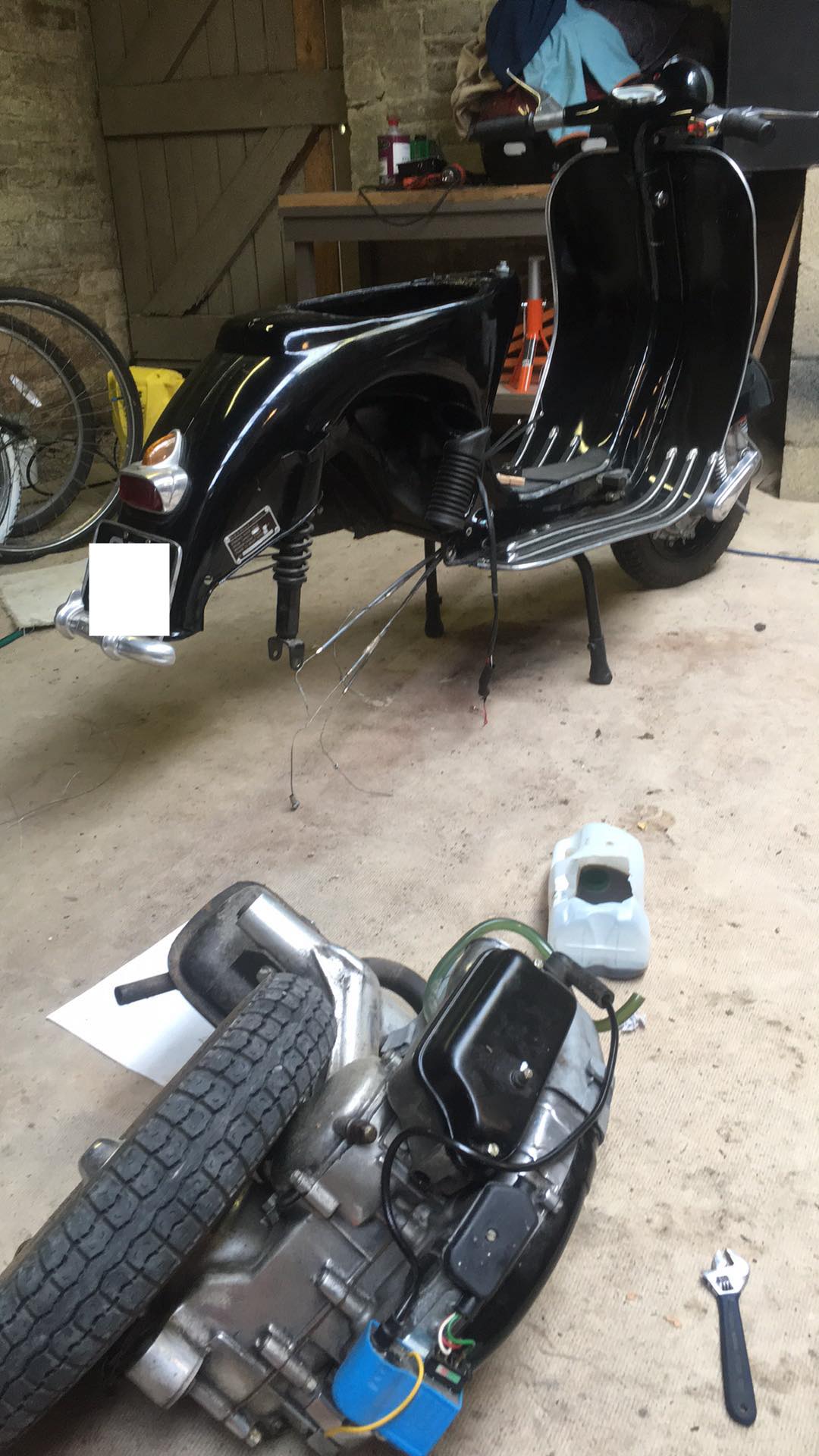
Now that I've wired up the battery, I need to mount it. I am going to put in where the fuel tank originally went. I think it will be possible to attach it directly to the top of the old fuel tank, meaning I can simply lift it in and out for maintenance.
This has involved cutting up the old tank, but I am hoping it wasn't the original anyway...
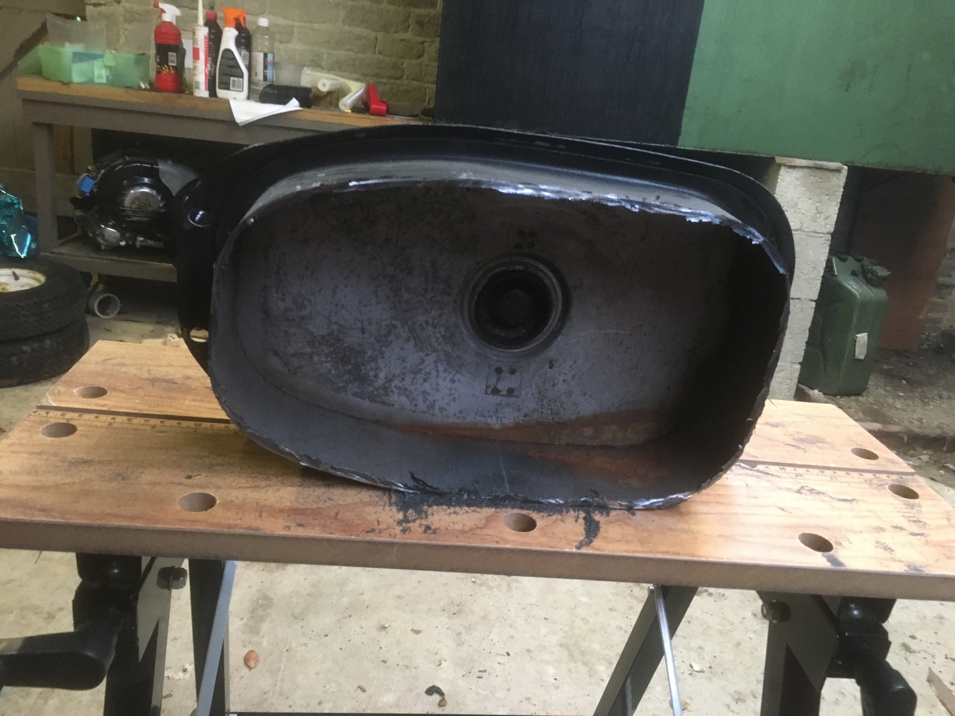 However, having looked at it. I worry it's slightly too large to fit in properly. The slope of the inside of the tank area means that the battery doesn't quite fit.
Oh well...
However, having looked at it. I worry it's slightly too large to fit in properly. The slope of the inside of the tank area means that the battery doesn't quite fit.
Oh well...
3D printed swingarm 3
27/11/2020
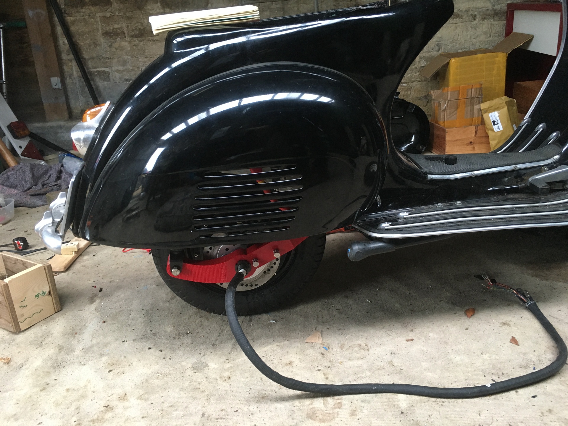
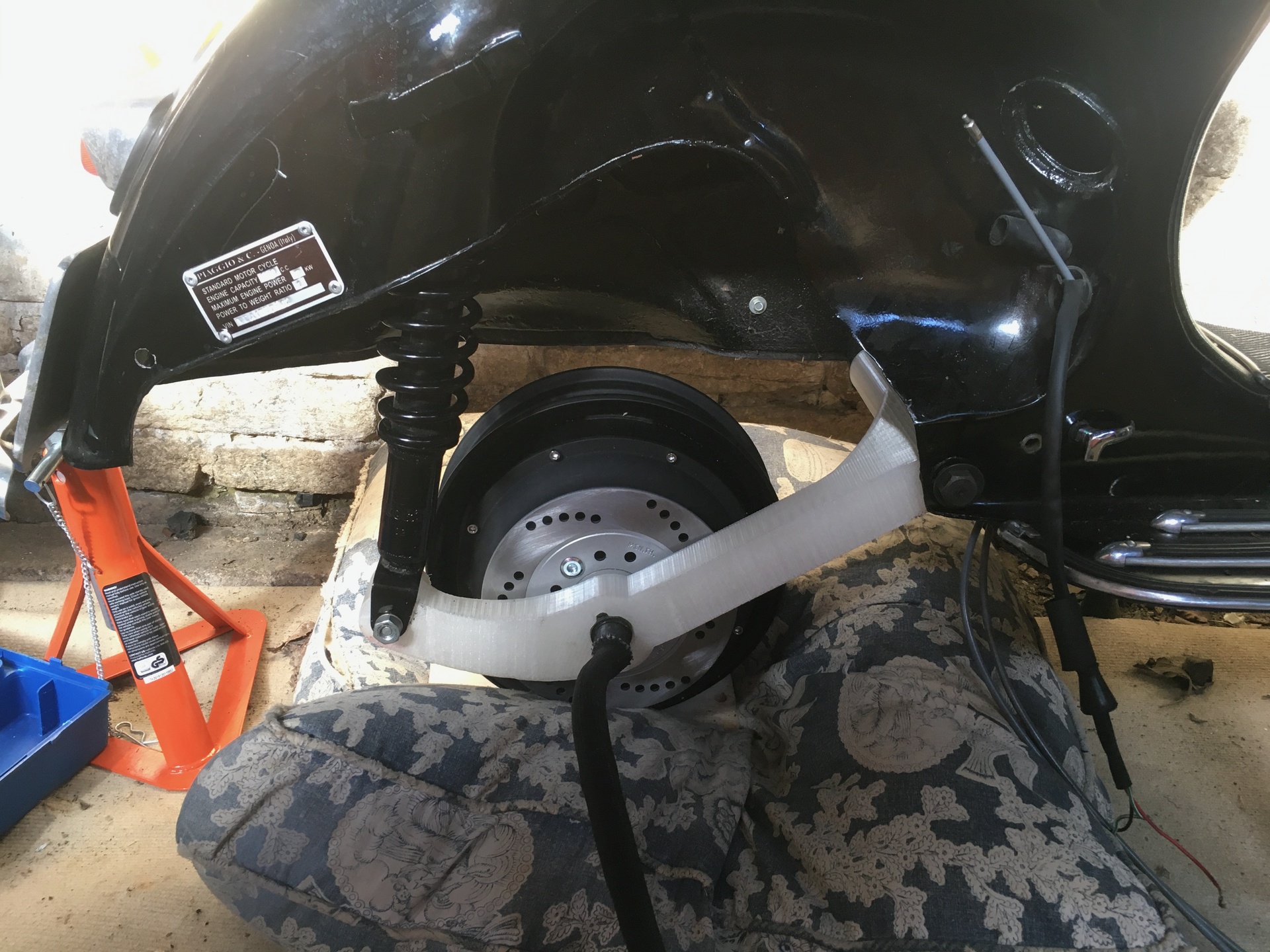
The final 3d printed test version of the swingarm arrived! It looks and fits great, especially with the fairing on. I think many people won't be able to notice the difference.
3D printed swingarm 2
07/11/2020
The next iteration of the 3d printed swingarm arrived. Having mounted a tyre to the wheel, we can finally see how it will look.
Controller plate
27/10/2020
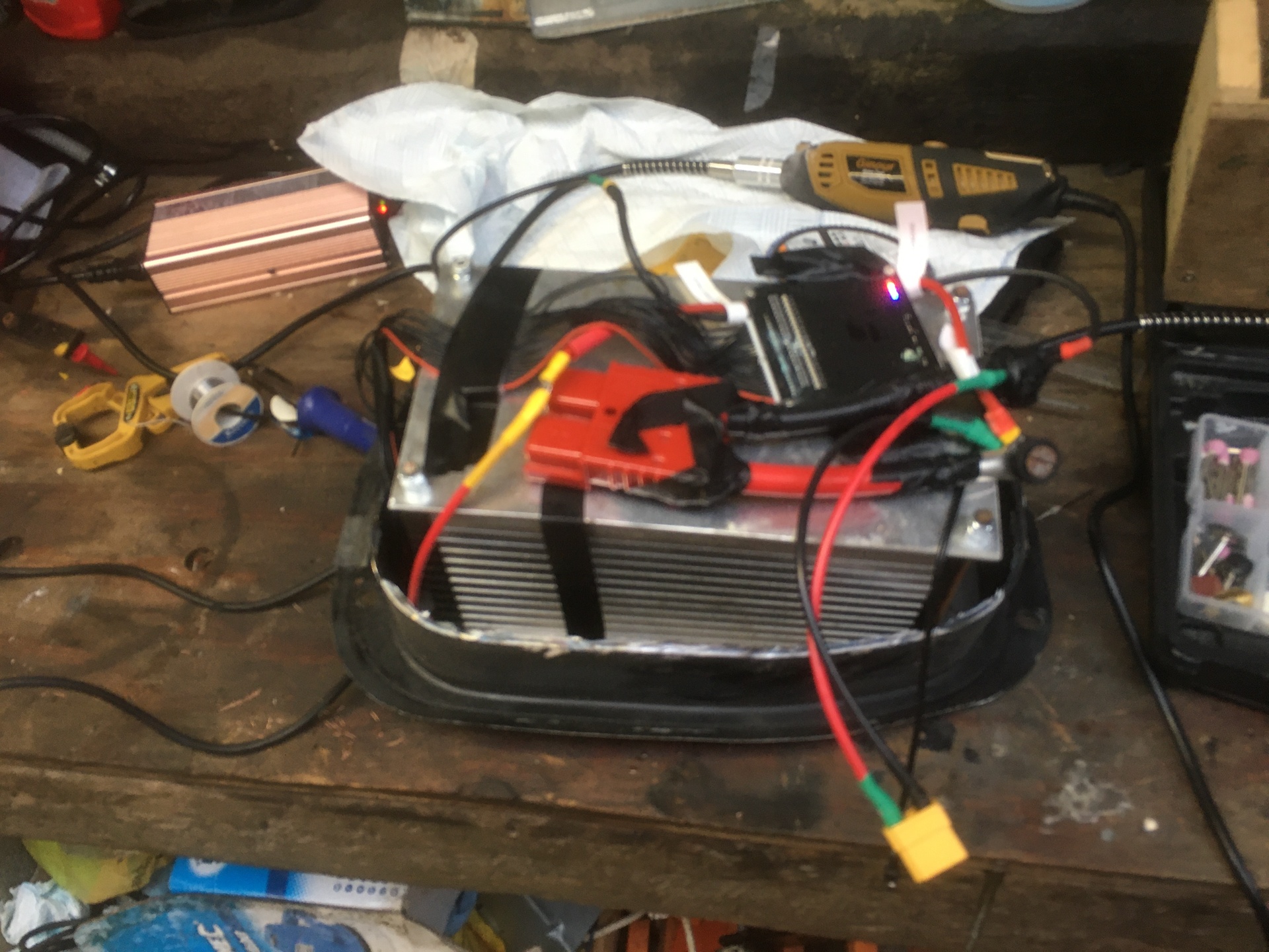
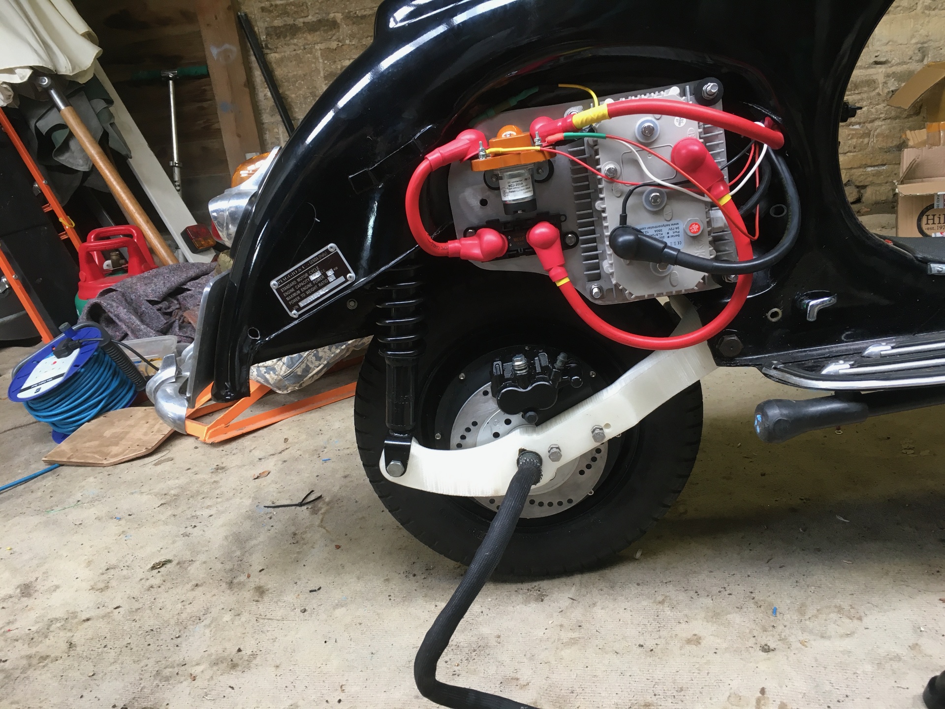
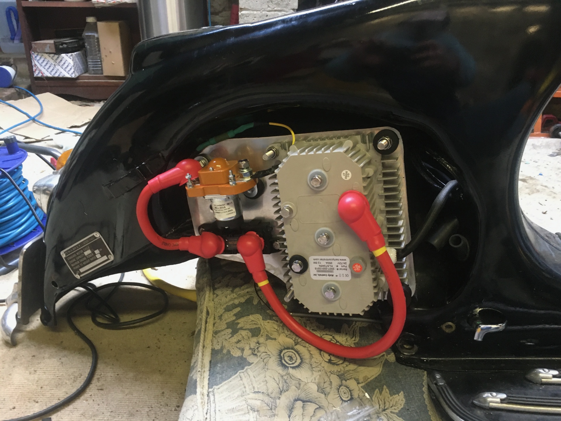
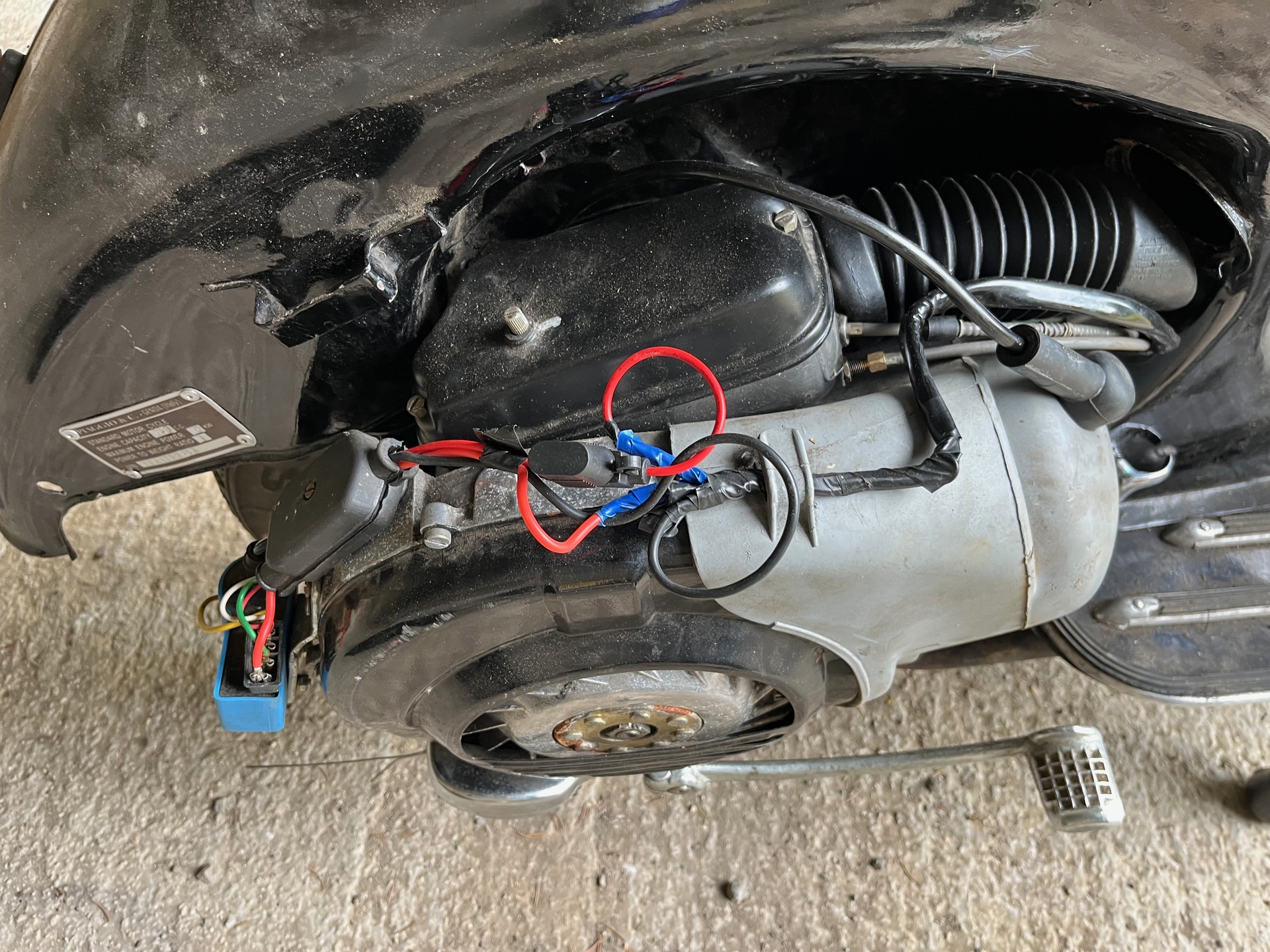
Removing the engine also frees up a lot of space under the right hand rear cover - where the original engine fitted.
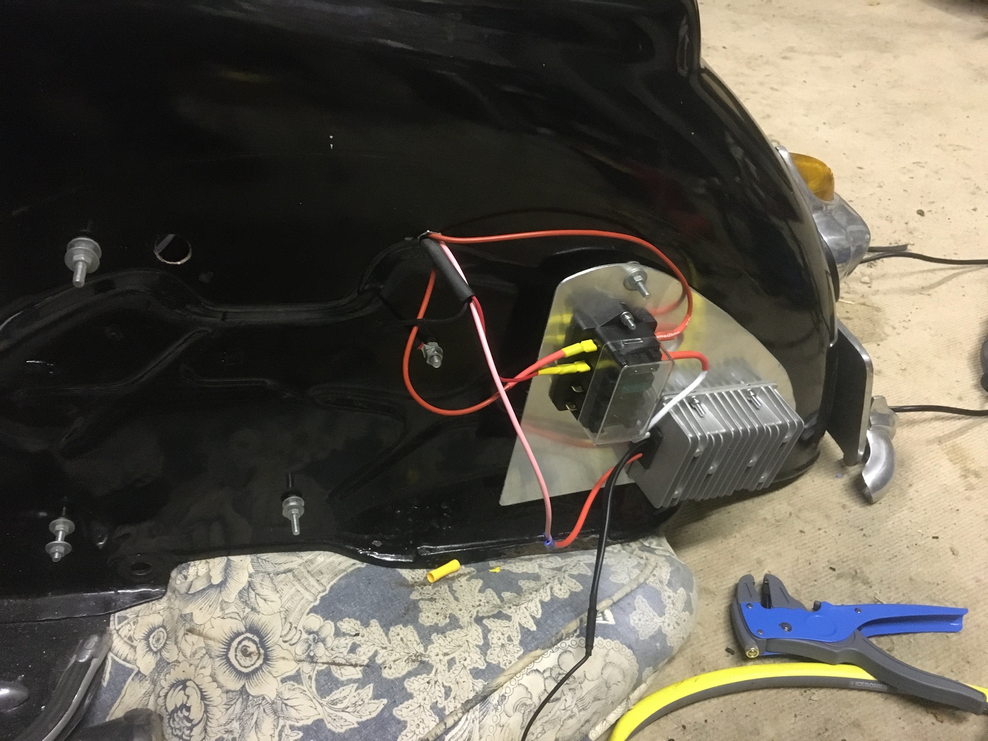
In that area, which is conveniently accessible by the removable, louvered cover, I'm mounting a plate on which to attach the high-voltage circuitry: the contactor, the high-voltage fuse, and the motor controller.
The three-phase motor wires will then run from the controller down the swingarm and into the motor.
 Meanwhile, the other fairing will contain the low-voltage circuit: the DC/DC converter, fuse box, and brake switching.
Clutch and LH bar
22/10/2020
A minor issue that needs solving is that the left-handlebar rotates. This originally allowed for changing gears (pull in clutch, rotate bar) but is now useless. I've completed a minor side-quest to fabricate a little bracket which jams the handlebar in the right place, meaning it can no longer rotate. What's next!
Rear brake
28/09/2020
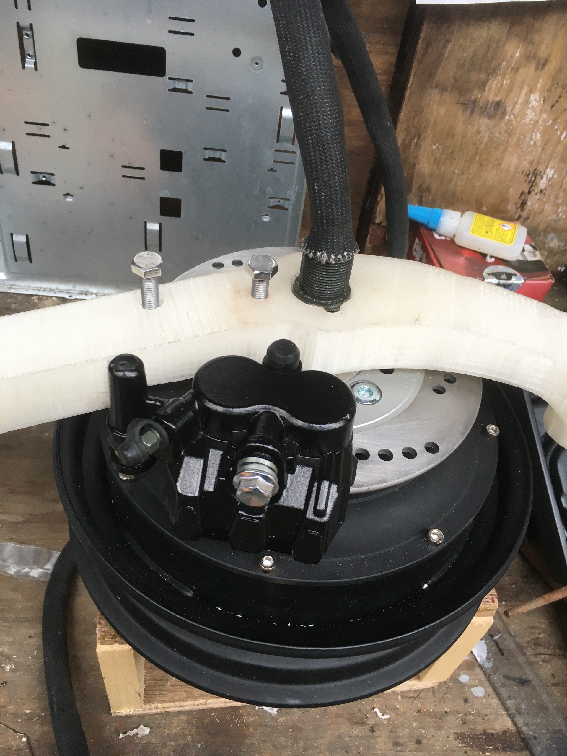
As well as the new motor being more powerful, the brakes will be massively improved on the e-vespa. The original rear brake used a 150mm drum brake. Perfectly fine given the size, weight, and power of the original bike. The motor, however, comes with a disc and I have sourced a hydraulic, two pot caliper. It being hydraulic does mean we will have to route a pipe and a master cylinder, but that should be possible. Originally, the rear brake was activated by the foot pedal. However, given the lack of clutch on this conversion, I want to use the left hand brake lever for the rear brake - just like on modern mopeds. The motor and controller are also capable of regen-braking, the ideal plan would be for the foot pedal to activate the regen: thereby allowing no-brake slowing and charging when needed or on hills.
3D printed swingarm test 1
27/09/2020
I received the first test of my custom CAD designed swingarm. I've not been able to put a tyre on the wheel yet, and I am also not sure if the PLA plastic would hold it, so the bike is still being held up by other means. However, in terms of size and accuracy things look pretty good! Some minor changes still to do: 1. Include holes for the brake caliper 2. Move the shock mount back and up to better recreate the original stance of the bike
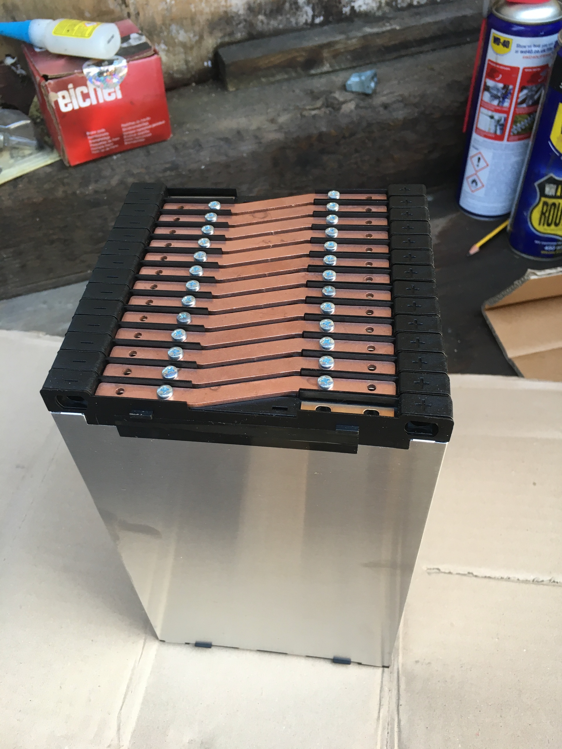
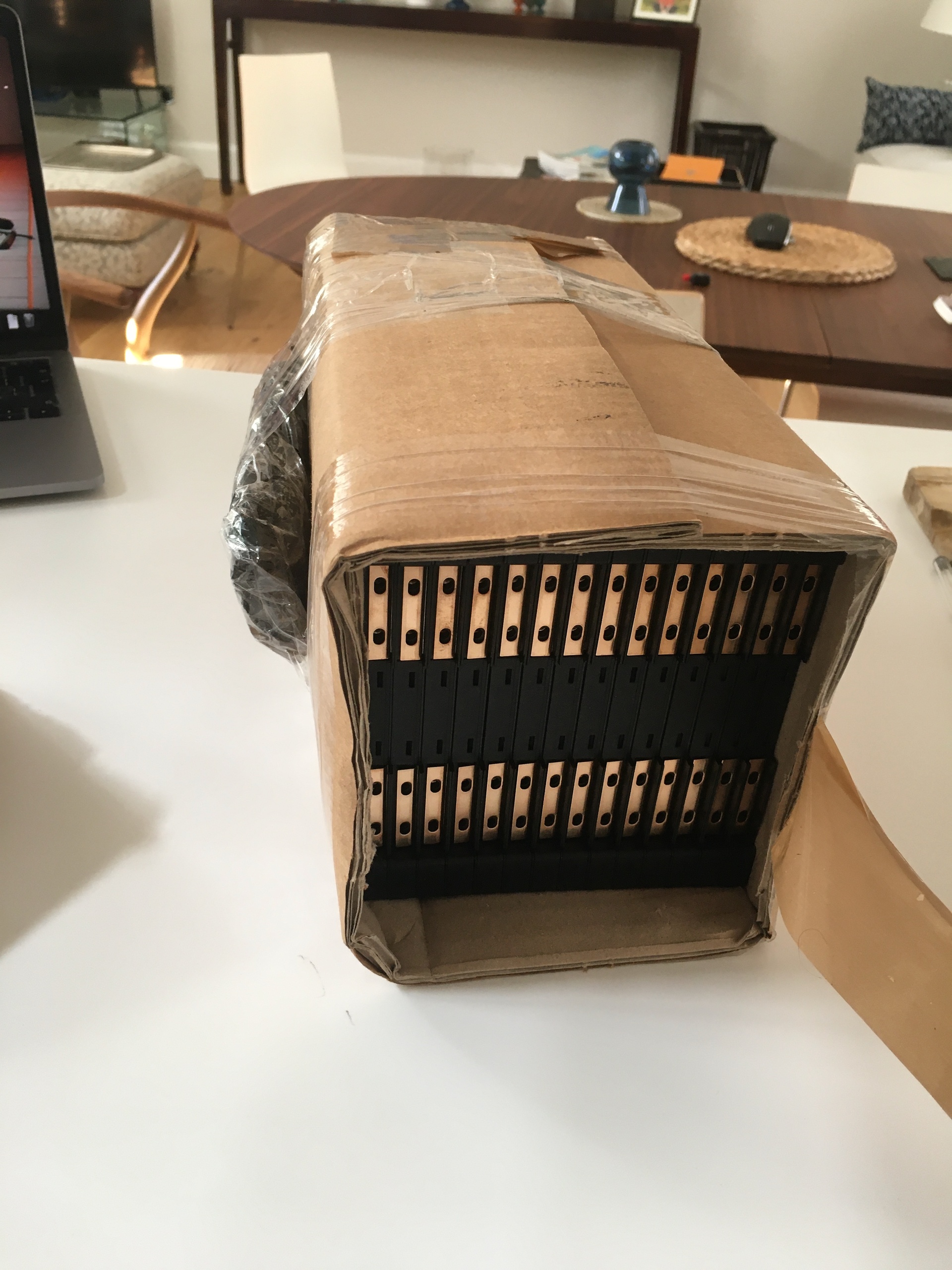
Found batteries
20/09/2020
I have found and bought some pouch cells. They are EIG C020 cells: each with 20Ah with a nominal voltage of 3.6V. I chose them for several reasons: 1. Pouch cells have a higher C rating than tube cells (mine can discharge at 5C continuous (i.e. 100A in my configuration) and up to 10C for 10 seconds, meaning you can get higher discharge rates without requiring a high capacity. 2. Mounting is easier because of their design: busbars can be bolted and they can be bolted together. This removes the need to spot weld (and, therefore, the need for a spot-welder). 3. The larger capacity means fewer cells are needed, as each has a relatively high Ah capacity. These batteries will run in a 1P14S configuration to get to 20Ah and 52V; rather than, say, 195 cells needed for a 15P14S battery of the same specs.
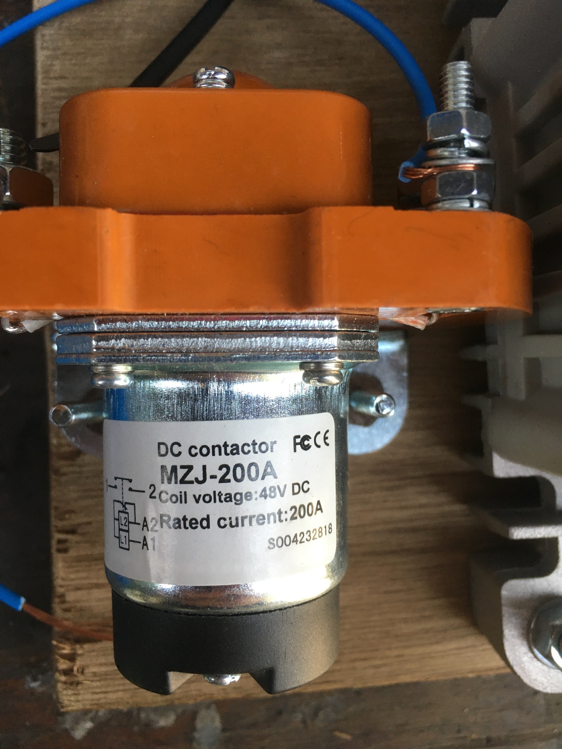
Contactor
12/09/2020
An important part of the safety system is the contactor: this connects the high voltage of the battery to the motor controller. Technically, this could be done manually: just bolt the wire onto the right part of the controller. However, it's a bit more convenient to use a remote one: essentially a high-current, high-voltage relay that connects the circuit when the key is turned. Obviously, it's important to make sure it's rated for the right voltage/current so using a standard relay isn't possible as it can't stand up to the sort of current that we need. Finally, a pre-charge resistor is needed to make sure no "arcing" happens within the controller. This is essentially a resistor that allows a little bit of current to flow through to avoid a huge inrush when the contactor is closed.
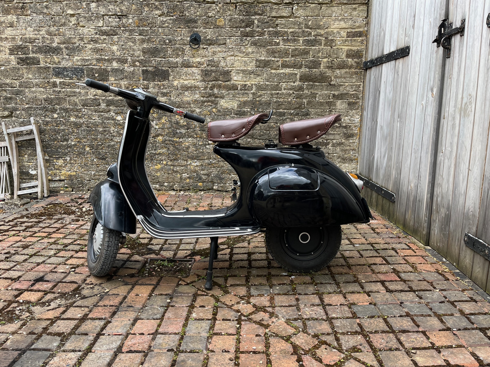
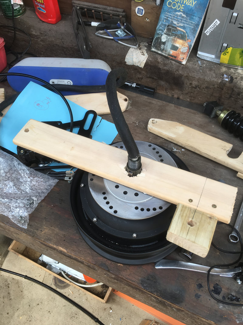
The swingarm
20/07/2020
So now that I have the motor, I have been looking at designing my swingarm. Many of the versions I have seen online use a double-sided swingarm, often using welded tubes and bar stock to create the right geometry. I've decided that I'd like to use a single sided arm to stay most faithful to the single-sided nature of the original bike. This will connect the hub-motor/wheel to the frame at the front and the shock absorber at the back. As with many scooters, the engine was originally part of the swingarm assembly, the gearbox output directly attaching to the rear wheel. It's not an obvious shape/size: it has to fit within the frame as built more than 60 years ago and have precise mounting holes for the motor, brake disc, and rear shock. I have mocked it up with bits of wood, to see if it will work, and it looks like it should be fine! Basic Swingarm version 1.0 is complete.
Battery thoughts
11/07/2020
I am still struggling to find a battery that can output at the Amps that I need it to. This is not an issue of capacity: i.e. how much power the batter contains, but actually an issue of discharge rate (measured as "C"s). Some batteries hold huge amounts of power, but can only discharge at very low rates (useful for applicants like battery storage), while other batteries hold less power but can output it much faster without disintegrating (useful for EVs or hybrids). The problem is obvious when doing the maths: 3Kw motor running at 48V requires a constant output of 62.5A from the battery (w = va). Even worse, at its peak of 5Kw, it will be pulling over 100A. All of this on top of (say) 5a for the BOS (lights, controller, etc). I had thought it might be possible to retrofit an e-bike battery, but many of them claim to only be able to output 50A continuous - not enough for what we want. I will probably need a custom battery then, and that means either I have to learn how to build a battery - or I hire someone else to build a battery for me. I have found these high capacity cells, which claim up to 3C (i.e. they can discharge themselves at three times their capacity - in this case 120A CC). I'm not sure if I would need to BMS these together or not - as I can specify high/low voltage with my controller. That would, however mean adjusting my wiring diagram to have it charge through my controller or an external BMS somehow.
6V AC to 12V DC
05/07/2020
Date: 5/7/2020
So, electronics problem. The current system for electronics is, I think (I forgot to test this before removing the engine), a 6 volt AC system. This is why the lights flicker seemly with the revs on the engine. The current coming from the stator on the engine is alternating, not direct. Therefore, when I tried to plug in a 6V battery this morning nothing happened.
After conversion I will be able to supply a content 12V DC current to the onboard system (what is sometimes called the Balance of System) via a 48V/12V DC/DC converter. (I think I will probably plump for this one). I'll probably be rewiring everything anyway, so this won't be an issue - there are not many wires to connect up (headlight, taillight, brake light is basically all you get) so it's not an issue.
The other consideration is that this is the perfect time to put indicators on the thing. BUT - I can't seem to find any indicators that are subtle or hidden or look good. I know the german 150s had big ones on the outside of the saddlebags (I am not sure what they're actually called), but I think they look horrible (see photo)! I think, for the moment, I will leave the indicators off. If I decide that I want them at a later point, I think it might be easy to simply remove the battery and rewire!
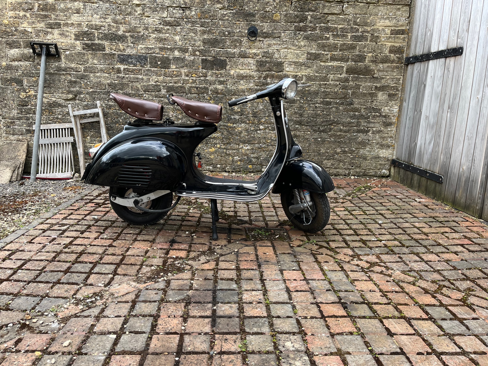
The Bike!
02/07/2020
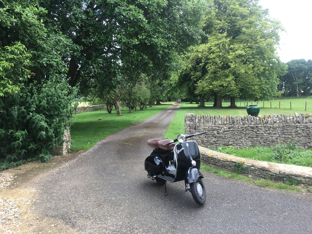
I am the proud owner of this 1964 Vespa 150! From what I can tell, it looks like its been recently restored. I believe that this happened in India (I understand that its a common move to ship these bikes to India to restore) and it was then shipped back to the UK. However, after looking at it I found a plate bolted to the rear right of the frame (just above the engine) with a VIN number stamped on beginning with VBA1T. My research tells me that this would, therefore, mean that the bike is actually a 1959 Vespa that has been mis-registered upon re-entry to the UK. The engine doesn't appear to be an original engine. It doesn't have a serial number on, but it does have some odd markings. I suspect it's a Chinese clone of a PX200 engine. At the moment it runs/drives (its lots of fun), but that'll change pretty soon.
Batteries
15/06/2020
According to 300mpg.org when doing a conversion, volts ~= speed. The advantage of converting a scooter and not a big bike, is that no one is expecting very much speed, so we can get away with a lower-voltage system. Even once you have decided your voltage requirements there are a whole load of other things to think about: 1. Lead Acid or Li-ion? Lead acid has the advantage of being cheaper, but the major disadvantages of being bigger, heavier and holds less power - and also if you drop the bike you’ll end up with acid all over your shoes! Li-ion is more expensive, has more difficulties with charging and discharging, but is lighter/smaller per KWh of capacity. 2. BMS Part of the problem with Li-ion batteries that they are made up of lots of little batteries, each of which must stay within the prescribed charge and temperature ranges or else and also be as close as possible to the other batteries in the pack. Most big or EV batteries are just clumps of much batteries wired in series and parallel to provide the current voltage and amp hour output. A BMS is a little circuit board that ensures that each of the cells is equally charged, and that the power is not being drained from one faster than any other. 3. Form factor Building a battery is, therefore, possible. It is probably the best way of getting the right size (as well as discharge rate and capacity) of battery we need. However, building a battery is also dangerous (high voltage) and requires specialised tools (like a spot welder). It would be best, therefore, to find a method of building a battery that doesn't require spot welding.
Motors
08/06/2020
QS motors - who apparently are fairly well known for their hub motors will sell me a 3Kw motor for about $250 dollars. The choice to go with a hub motor is also obvious given the choice of bike: the vespa is not chain driven, the engine sits on the swingarm and provides direct power (via the gearbox) to the wheel. Going with a central motor would mean building a whole new drive system for the vespa. I have seen a post by someone who removed the engine and bolted an electric motor where it used to be, which would retain the gearbox and drive chain, but this seems unnecessarily complex. I think 3Kw is fine, given it's already more than the original 2-stroke put out. Though, it does not sound like a lot, given that my motorbike has 35Kw and is still underpowered. However, electric Kw are different from petrol Kw. The torque is always and instantly there, no waiting around or changing gear for that power. I am fairly sure that 3Kw is all I need as I am only aiming for a top speed of about 30mph. Helpfully Retrospective publish their motor’s stats as a 3Kw motor, and they claim it is of similar power output to that of a 125cc engine. So I feel fairly secure in my choice and keeping the motor power low will help me keep the battery low. The motor controller (I think I will use a Kelly Controller KLS7245N) actually costs more than the motor (somehow!), and postage is about $150. so about $700 for the whole kit (not including the batteries) from QS motors.
The Plan
01/06/2020
Electric conversions are a good idea for classic conversions: electric motors are much more reliable and often provide more power for less weight and size. I think this is especially true for classic motorcycles and scooters: small but powerful electric motors can easily replace ancient 2-strokes and batteries don't need to be enormous Tesla (or other) packs. I think an excellent conversion would be for a classic Vespa: they look good, they're readily available, and they came underpowered so an E-conversion will only improve things. What's more, the bodywork and fairings give lots of space to cram in batteries and other required electronics. I am not, however, the only person to have had this idea: - A company named Retrospective Scooters sells a vespa E-conversion kit on their website for £3500. - This guy in California making up swingarms in his garage. - Another forum post about a 5Kw conversion. - Some good examples in this thread. These are helpful in planning: the Retrospective kit seems to comprise of an electric hub motor, a motor controller, a battery and some wires - easy!
So, The Plan:
- Build an electric vespa for less money than the kits you can buy off the internet!