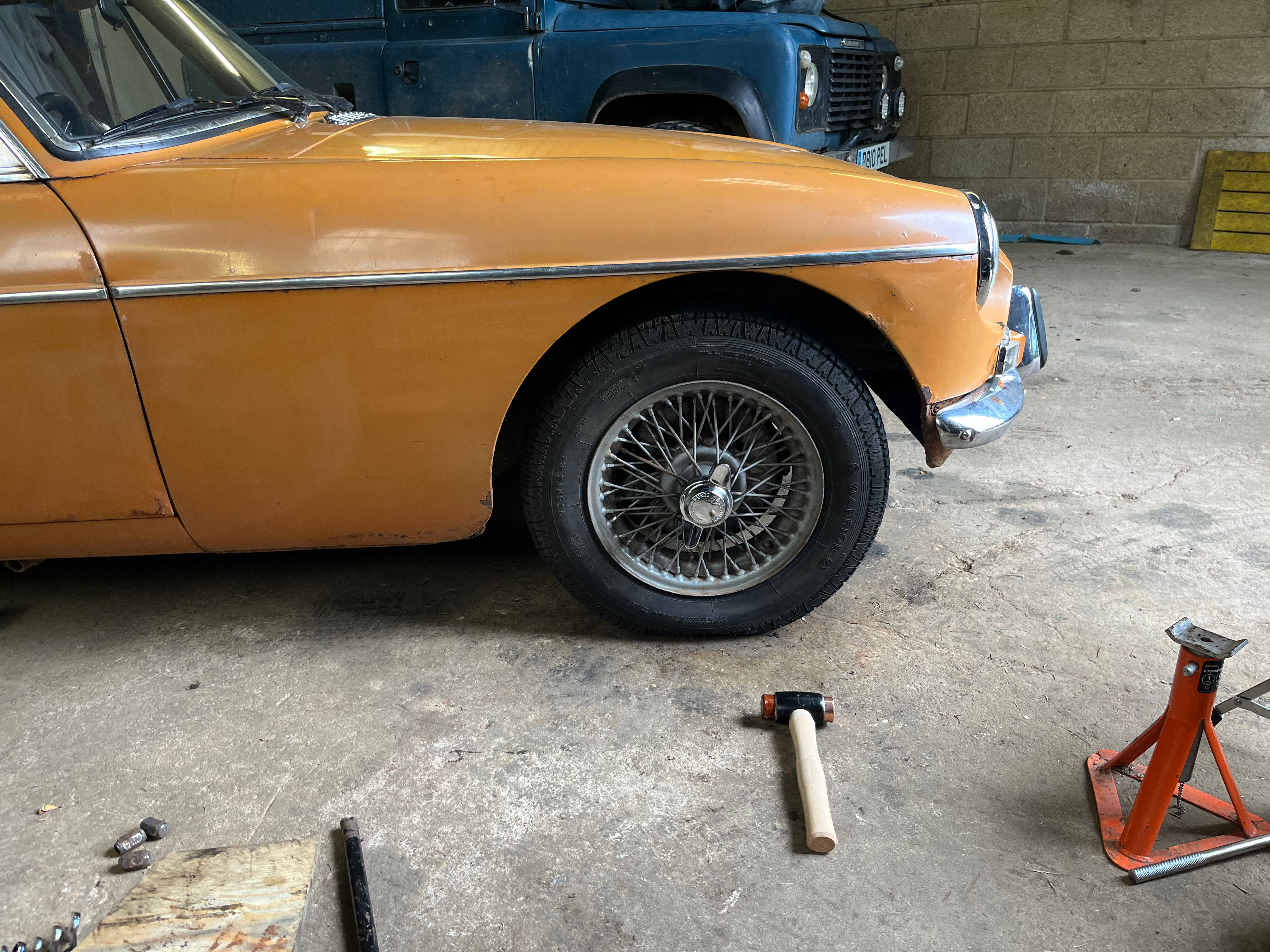
Wire Wheels
The old "rostyle" wheels have now been swapped out for more "classic" wire wheels. This was done using the MGBHive conversion kit.
 The theory is to replace the wheel hubs, removing the four-stud pattern bolt ons with the splined-and-threaded shaft needed for wire wheels. The kit includes all you need to do this, including new bearing kits for the front.
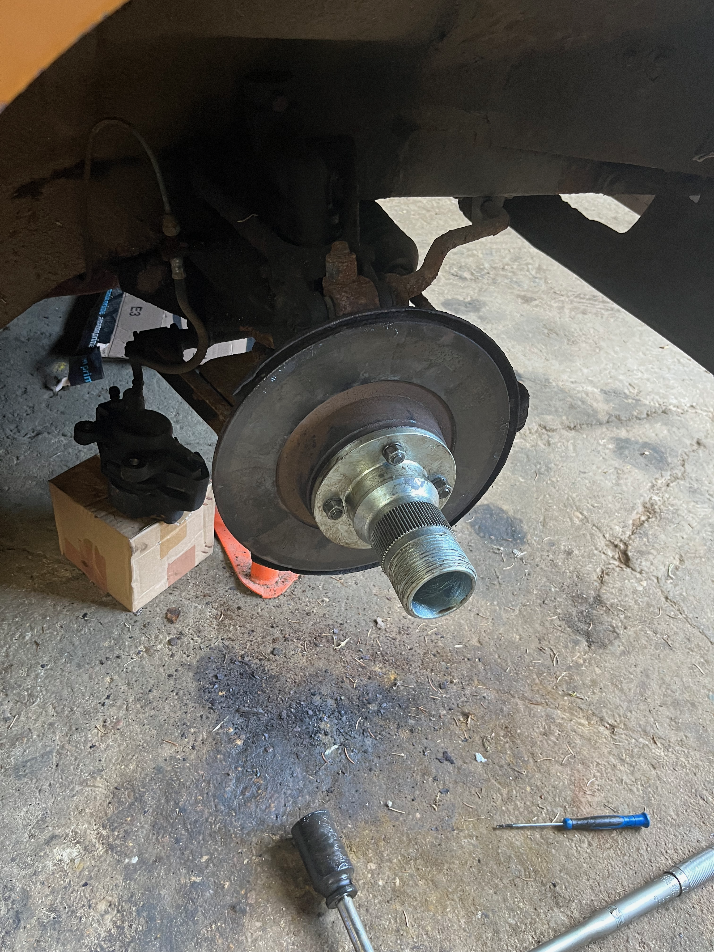
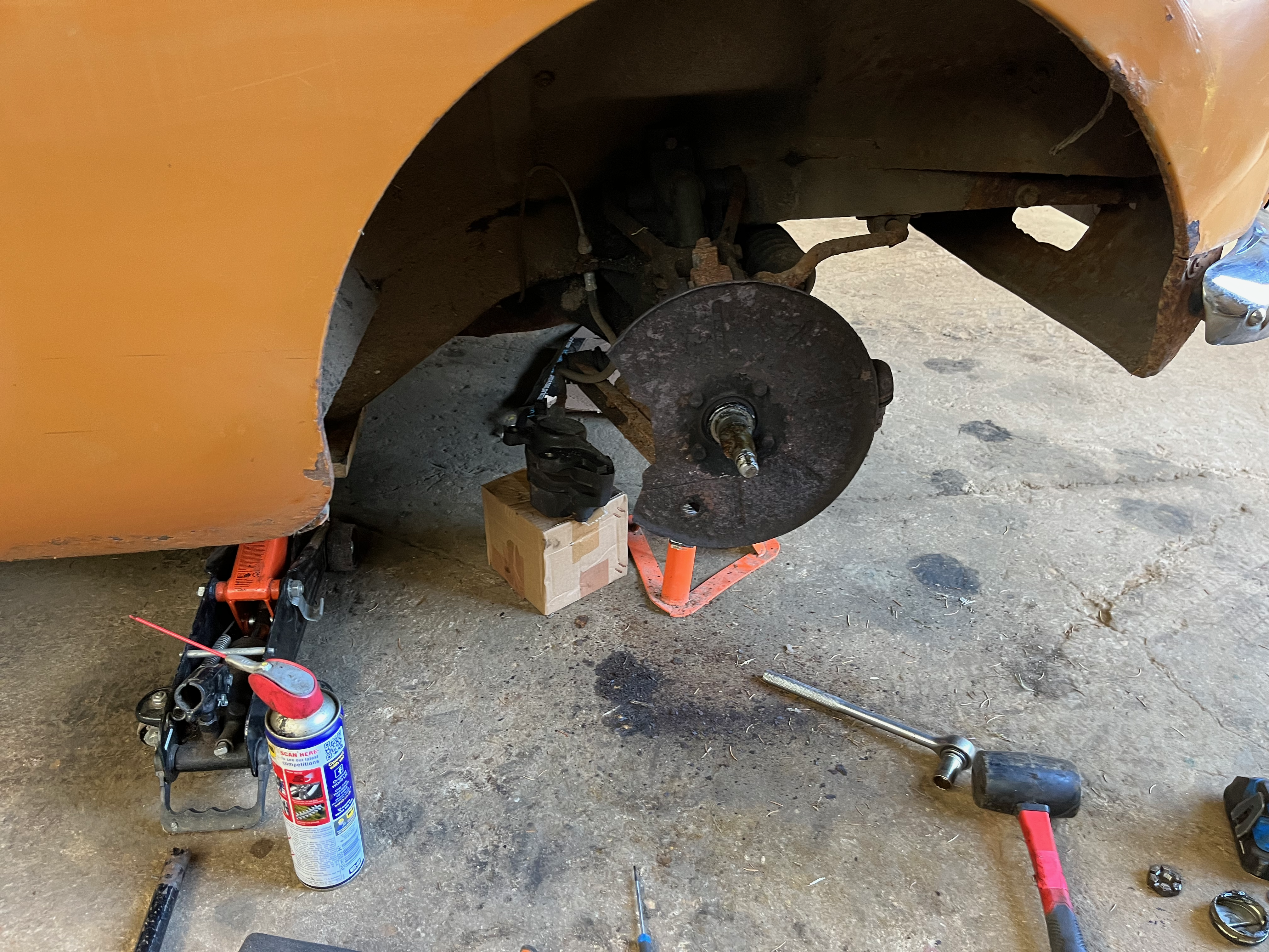
Rear Wheels
The rear wheels are the easier of the two sets to do, simply: 1. Jack up the car, release the handbrake (having chocked the car), and remove the wheel. 2. Remove the split pin in the castellated axle nut (using a 1-5/16th deep socket), the axle nut itself, and the split "collar" that sits behind it. 3. Remove the brake drum (2/3 can be done in either order) 4. Pull off the wheel hub from the splines it sits on - I used a bearing puller tool we already had, but the MGBHive instructions recommended reinstalling the brake drum backwards and using a mallet. 5. Slide on the new hubs - I used a small amount of copper grease on the splines. I was not sure if grease was a bad idea (given the proximity to the rear brakes), but I thought binding on would be bad. It's important to make sure you slide it on in a orientation that allows you to access the thru-holes for the split pins. Double check you can do this before continuing. 6. Attach the brake drum to the new hub, using the supplied four bolts - it helps to have an assistant depress the brake pedal for this, and the next bit. 7. Reinstall the collar and castellated nuts (instructions spec-ed 150lbft, but I just tightened it as far as I could), as well as the split pin. Bend up the split pin. 8. Grease the wheel splines and the threads. 9. Slide on wire wheel, and thread on spinner.
Simply repeat for the other side.
Front wheels
Important: Do not tackle without an ample supply of paper roll, degreaser, and gloves. You will be messing around with grease that may have been there since the factory, so watch out!
The supplied instructions are pretty accurate for this: 1. Chock, jack up, and remove wheel. 2. Remove the two rear bolts from the brake caliper, which attach it to the hub assembly. These are on the "back" of the assembly, are require some force to remove. I placed the lose caliper on a box at the back of the wheel-well, so that there was no force on the brake line. 3. Pry off the "cap" at the end of the axle. Use a large set of pliers/pipe wrench and a small flat-head screwdriver. 4. Remove the split pin from the castellated nut, and undo nut. Making sure to check for notched washer that might come off with the nut. KEEP BOTH SOMEWHERE SAFE. 5. Pull the hub and disc from the spindle. Use a sudden, firm action to bring as much of the internals off at the same time. 6. Remove the disc from the hub, retaining bolts, washers and nuts. 7. Pry apart the old hub. Being careful of the aged grease. Ignore both sets of bearings, and the rear oil seal. Make sure to get the spacer (which resembles a gear-lever knob), and the two shims that are stuck to its thin end (or the inner of the smaller bearing). Throw the rest of it away. 8. Don fresh gloves and insert the new bearing races into the new hub. I used a vice to press them into place. The larger on goes on the rear, and the smaller on the front. 9. Attach the disc to the new hub using the four nuts/washers/bolts you removed from the old hub. Tighten as much as you can. 10. Insert the spacer, and the inner, larger bearing (after packing with grease), as well as the rear oil seal. The side with the U channel goes facing towards the bearings. Pack the whole area with as much grease as you can. 11. Clean the spindle of all the old grease as you can mange. Making sure to re-install the "collar" which sits at the back of the splindle and spaces the hub/disc away from the rear shield. 12. Slot the hub assembly onto the spindle. Use firm, sudden movements. 13. Slide on the shims you removed from the old hub assembly, followed by the outer, smaller bearing (after packing with grease). 14. Follow with the notched washer, and the castellated nut. 15. Tighten the castellated nut to ~50lbft, then keep turning until a gap is free to insert the new split pin. 16. Insert and bend the new split pin, followed by the grease cap which just sits in the tube. 17. Grease splines and threads of hub, attach new wheel and do up spinner.
I found this video helpful in understanding the manner and order in which to insert bearings, even if he is doing it on a four-bolt hub.
Thoughts
With both wheels, I was unsure how much force is needed when doing-up the spinner on the wheel. I just hammered it home until I felt it was on properly, then gave it another one for luck. I believe they can be attached too tight, but better that then too lose!
Once you've done one wheel, the other side is a piece of cake.
These wire wheels seem smaller than the old ones, perhaps it is the tyre-size? I'll be getting new tyres anyhow so I will try and get the largest sidewall I can.
To fix: Wheel clamp is now too short. To fix, I will need to get a small section of threaded bar (3/8ths - 24) and a coupling bolt.
I need new tyres - what are the right sizes? 175/56R14? Can I use the tyres I removed from the old wheels - should I?
Things it would have been good to replace while I was there
- Front & rear wheel "shields" aka "dust covers"
- Rear wheel bearing (RH seemed a bit "weepy")